Constrain nodes displacements in 2D
It’s passed a list of dictionaries. There are two options for constrain nodes displacements:
Constrain nodes displacements by column
Constrain nodes displacements by coordinate
Hint
It’s possible combine and use both options.
Constrain nodes displacements by coordinate
The dictionary has the following keys:
“x_coord”: coordinate in X-axis.
“y_coord”: coordinate in Y-axis.
- “constrain_disp_x”: indicates if the node displacement is contraint in X-direction.
If 1 constrain the node displacement in the X-direction.
If 0 don’t constrain the node displacement in the X-direction.
- “constrain_disp_y”: indicates if the node displacement is contraint in Y-direction.
If 1 constrain the node displacement in the Y-direction.
If 0 don’t constrain the node displacement in the Y-direction.
In the example is constrained the node displacement at coordinate (0, 0.7).
restri_matrix = [{"x_coord":0, "y_coord":0.7, "constrain_disp_x":1, "constrain_disp_y":1}]
The resulting mesh is shown in figure 5.
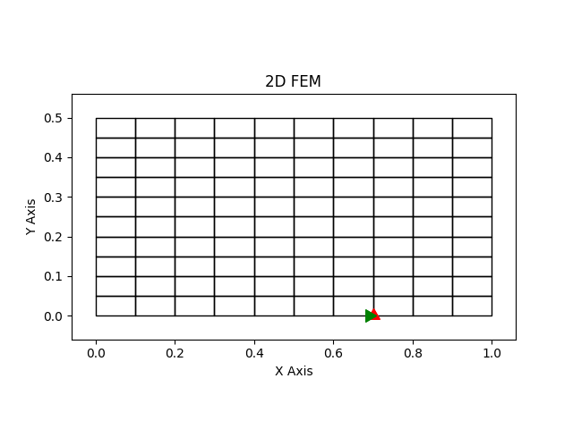
Figure 5: Mesh with X and Y axes constrained of the eighth node.
Constrain nodes displacements by column
The dictionary has the following keys:
“coord”: coordinate.
“axis”: Direction that the node displacement is constraint. It can be: 1 (X-Axis) or 2 (Y-Axis).
“eps”: Margin of error.
- “constrain_disp_x”: indicates if the node displacement is contraint in X-direction.
If 1 constrain the node displacement in the X-direction.
If 0 don’t constrain the node displacement in the X-direction.
- “constrain_disp_y”: indicates if the node displacement is contraint in Y-direction.
If 1 constrain the node displacement in the Y-direction.
If 0 don’t constrain the node displacement in the Y-direction.
restri_matrix = [{"coord":0.2, "axis":2, "eps":0.001, "constrain_disp_x":1, "constrain_disp_y":0}]
In the example is constrained all the node displacements in X-direction with Y = 0.2.
The resulting mesh is shown in figure 6.
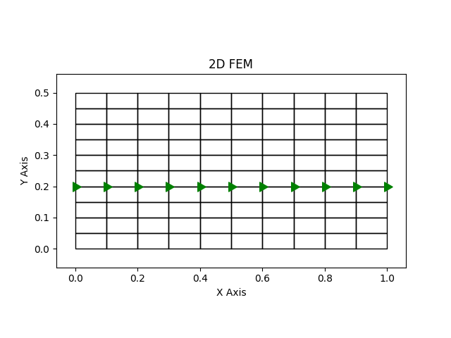
Figure 6: Mesh with X-axis nodes constrained with Y = 0.2.